
|
Back to Contents | |
|
|
||
John Parker jparker3@twcny.rr.com
A Primer on Supercharger Systems
The basic principle of improving performance with a supercharger is the same as with any performance engine: to cram as much air/fuel at the correct mixture into the cylinder as possible. With a normally aspirated engine (NA) the suction of the intake stroke creates a vacuum that draws the air/fuel mixture through the carb or throttle body. Everything is done to facilitate the flow of this air, included complicated tuning of intake lengths, etc. With a supercharger, higher power is created by pressurizing the intake track. This allows more of the air/fuel mixture to enter the cylinders.
What limits the amount of air/fuel that can be pushed into the combustion chamber? Well the main limiting factor, besides the octane of the fuel available, seems to be a phenomena known variously as detonation/pinging/knock. This unwanted pre-ignition of the A/F mixture causes high pressure waves in the combustion chamber that can be very destructive. In fact, an engine subject to severe detonation can be destroyed in minutes. Fuel octane ratings are based on the fuel's ability to resist detonation.
The higher the temperature of the mixture and the higher the compression ratio, the more likely it is that there will be detonation. Conversely, a lower temperature mixture and lower compression ratio allows for higher intake boost pressures before detonation is encountered, given the same octane fuel and other conditions. Another important factor is ignition timing. Advancing the ignition timing increases the chances of detonation while retarding the timing decreases it. Without trying to get into a lot of theory, by lowering the compression ratio, lowering the charge temperature, reducing the ignition advance, and using higher octane fuel, higher boost pressures can be run. Retarding the ignition and reducing the CR can also reduce power and engine efficiency/gas mileage, so there is a trade off.
Another complicating factor is that whenever a gas is compressed the temperature is increased. So we have a situation where the very action (compression) that will increase the power will also create the heat that both reduces power and increases the risk of detonation. The key is to set up a system that maximizes the favorable factors and minimizes those that are unfavorable.
Probably the most important of these factors is the selection of an efficient supercharger.
Superchargers can be rated in their efficiency based on the amount they heat the gas as they compress it. The most efficient SC is the one that, all other things being equal, will generate the least heat per PSI of boost, and uses the least power to do it.
Ignition systems can be tailored to be advanced when there is no danger of detonation, and to retard the ignition when either detonation is more likely or actually occurs.
Combustion chamber shape can also contribute to the detonation problem. Certain chamber shapes are simply more prone to detonation than others.
Intercoolers are used in most performance turbo applications to cool the air once it is compressed. One of the comparative disadvantages of turbochargers is that the use of exhaust gasses to rotate the compressing impeller puts the intake charge in close proximity to high heat and promotes the increased temperature of the intake charge. With superchargers, if they are efficient and fed air at a reasonably low temperature, the discharge temperature can be low enough to eliminate the use of an intercooler and its associated plumbing. Designing a Supercharger System to take the above factors into account
1) The cool air charge
On the 1800E and ES, there is a cold air intake with the air filter located to the side of the radiator, not behind it. This is a much better system than taking in air at under-hood temperatures, and partly accounts for the better performance of these cars. Look at a photo of an old Ferrari and you will find a scoop on the hood to bring in cold air to the carbs. Efforts should be made to adapt a method of cold air intake to any performance engine, particulary one that is turbo or supercharged.
2) Supercharger efficiency
3) Ignition systems
A number of different methods are used in different systems to deal with this issue, these include:
4) The Intercooler
The two basic types of intercooler are air to air and water to air. The air to air type is most common as used in Volvo 240 and 740 turbo systems. The heated air exiting the compressor is ducted to a front mounted "radiator," or more properly a "heat exchanger," where the charge air is cooled by the cooler, ambient temperature air forced through the intercooler by motion of the vehicle and/or fans. The chief disadvantage of this system is the space taken up by the comparatively large diameter ducts used to transport the air from the compressor to the intercooler and back to the engine's intake manifold.
The second type is the water to air intercooler. This consists of two heat exchanger units. One is a front mounted radiator, mounted in front of the vehicle's normal radiator. There, a liquid is cooled by outside air going through the radiator in the same manner as in the vehicle's cooling system. An electric pump pumps the coolant from the front mounted radiator to a second heat exchanger unit that is normally attached directly to the compressor and/or the engine's intake manifold. There, the charge air is cooled by exchanging heat with the liquid coolant. The disadvantage of this system is the need for two separate heat exchanger units. The advantage is one of packaging in terms of the size of the units, water hoses verses air ducts, and the increased efficiency of the water to air heat exchange. Applying the above factors in designing a system for vintage Volvos
Keeping in mind the primary KISS principle, I took a shot at applying the above factors to a system for an 1800/122/544. An important additional factor was to control costs both in producing a single application and in making it possible to reproduce it economically for others. Complicating the issue is the number of different types of setups that could be used. There was an almost bewildering array of choices.
The choice of the Weber carb was simple -- it is readily available and marvelously adaptable. What we needed was a carb that could be tuned over a wide range of conditions with jets and other parts that were readily available. The 45 DCOE Weber fit this requirement, although it was somewhat more difficult to install than an SU. Additionally, there are larger and smaller sidedraft Webers readily available if we initially misjudged the fuel/air requirements.
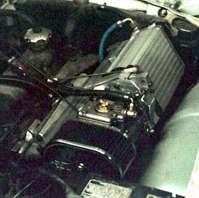
The initial installation was done by milling carb and manifold adapters from solid aluminum. It took quite a few attempts to get all of the angles right so that everything fit together and also fit under the hood of an 1800.
The drive belt had to be set up so that it would clear the generator, the water pump, the fan, etc., and is driven off a modified crank pulley. The current prototype setup will not accommodate air conditioning. A drive system with AC would just be a little more complicated, and we were trying to keep it as simple as possible. At first, we misjudged the amount of tension required on the belt and kept getting belt slippage until we installed a proper tensioning system that was not dependent on muscle power to adjust. (Boost pressure jumped more than 5 lbs. with the proper tension, but this caused a problem -- see below.)
Linkage modifications were also necessary, but reasonably simple. However, the initial setup had to be modified several times to make sure that the throttle plates would both close and open completely when installed in the vehicle.
The SC requires an oiling system for its internal drive gears, and this meant that we had to tap into the engine's pressurized oil system and make up a return line. A "T" from the line to the oil pressure gauge easily solved the supply problem. The return line was a little more complicated, as we did not want to have to take the engine apart as would have been necessary to tap into the oil pan, or disable the oil temp gauge as would have happened if we had used the oil temp fitting in the oil pan for a return. Initially, we used the dip stick hole as the oil return location. Subsequently we tapped into the front cover and bolted in a fitting. This turned out to be a simpler and much more compact installation.
As I reported previously, right out of the box we were able to get 0-60 times in under 8 seconds, even though we were getting a significant amount of hesitation due to a lean carb condition under acceleration. Initially we just could not find main and accelerator pump jets big enough. Some we eventually found, some we drilled out. Further testing and tuning brought the time down to the low 7 second range. Although the car was a pleasure to drive on numerous trips through the countryside, we were still encountering belt slip and some hesitation. A new belt tensioning system and a final rejetting were designed to cure the last of the problems.
Unfortunately some of our fixes turned out to be our undoing -- at least temporarily. With the new belt tensioning system, we were fairly sure we had licked the belt slippage problem. We had also discovered that the throttle linkage was not allowing the carb throttle plates to open all the way, and made adjustments to allow them to open fully. I found a longer accelerator pump rod and matching spring that gave a longer and larger shot of fuel on opening the carb throttles.
With these modifications, we looked forward to significantly improved acceleration, and it certainly felt like it when I pulled out onto the road. No hesitation this time -- just pure power -- much improved. After the first acceleration run, I looked down to the boost gauge and was shocked to see it read 15 lbs., and this was coming off the throttle. I turned around to make another run, hit the throttle hard at about 20 MPH in second gear and power shifted into third, chirping the tires. Then boom, pop, water in the cockpit. Shut it down and coast back to the shop. The head gasket had blown, letting boost pressure into the cooling system which burst an old heater hose. Boost pressure had jumped unexpectedly when we had eliminated belt slip with the improved belt tension system. With changes to the linkage, we were finally getting full throttle. We were suddenly running a much higher pressure than we had ever planned to try with the stock engine.
It turned out to be only a head gasket, and the torque on the head bolts was way below spec. Remember, this was a completely stock engine that came with the car. We had purposely not done anything to it in order to see how the typical engine would react to supercharging. What we found out was that the stock engine will take moderate boost very well, but it gets questionable above 10 lbs. Further testing will tell us what it takes to run 15 lbs. boost. Having felt it once, I won't be able to settle for less.
|
 In the first installment in this series, I reviewed Volvo's performance and competition history, and described my project to build an ultimate vintage Volvo street car. The second installment reviewed the reasons for choosing a supercharger for the project. This is a follow up article to the first two. It will describe the basic theories of supercharger/turbo charger systems and will describe our prototype supercharger setup.
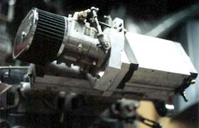 What I came up with is a carburated, draw through system using a single Weber 45 DCOE Carb and a Lysholm principle dual rotor supercharger. The draw through system was chosen as much for ease of packaging the system as anything else. It also allows for the use of a single carb, whereas a typical blow through system would have required two carbs and more room. By choosing a supercharger with a high thermal efficiency, one that heats the charge least as it compresses it, we were confident that we could design a system that would not need an intercooler -- another serious complication.
 (There would have been less problems if I had done the initial work on a 544, 122, or 140, but then the finished product would not have been transferrable to the smaller engine bay of the 1800.)