
|
Archive Index | Current Issue | |
|
|
||
Phil Singher editor@vclassics.com This is intended as an introduction to our transmission rebuild article, but may also be of interest to those of you who are simply curious about what goes on at the far end of your shift lever or are planning on having a rebuild done by a shop.
Description:
 (Photo taken in my shop: the "Chamber of Horrors")
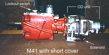
The M41 is much the same gearbox adapted to drive a Laycock de Normanville electrically-actuated hydraulic OverDrive unit attached to the gearbox's rear and sharing its oil supply; essentially a fifth gear. Two variants of OverDrive were used: the D-type into the 1968 model year and the more robust J-type thereafter. It is not possible to bolt an OverDrive unit onto the M40 -- the M40 and M41 mainshafts and rear bearing housings are quite different.
In the transmissions on which we've thought to look (one hesitates to make this a blanket statement...), the filler plug is located higher in the M41 case than in the M40. In other words, you might hybridize an M41 mainshaft and bearing housing into an M40 case and make it run, but you'll never be able to check the oil level once it's in the car. It's not worth the doing.
Shifting is accomplished by a lever mounted through the top cover of the transmission. There is no external linkage, nor is the linkage adjustable internally in any way.
In all styles, the under-the-cover end of the shifter passes through a spring-loaded plate which centers the shifter in the 3rd - 4th gear axis if no pressure is exerted by the driver. The shifter engages one (and only one at a time) of three hefty rods running fore and aft in the top of the case -- one for 3rd - 4th selection, one for 1st - 2nd selection and the third, of course, for reverse gear. Each rod is held (with no great force) in neutral or in fully-engaged position by a spring / ball / detent arrangement at its forward end. These simply keep the rods from drifting due to vibration or G-forces and add a little feel to the shifter -- they are not in themselves sufficient to prevent "kicking out of gear" due to other defects.
In the M41, OverDrive is selected by passing electrical current to a solenoid mounted on the OD unit itself (varying switches and wiring layouts were used). In stock installations, that current must pass through a second "lockout" switch on the gearbox cover which is closed by a fitting on the 3rd - 4th gear selector rod, thus enabling OD selection only when in 4th gear. The lockout switch may be bypassed with a little creative wiring, resulting in eight selectable forward gear ratios -- unfortunately, the OD may then also be engaged in reverse gear, resulting in the destruction of the OD unit (a word to the wise...).
The solenoid routes high-pressure oil (the pressure being produced by a pump inside the OD powered by an eccentric on the gearbox mainshaft) to a series of pistons and valves which, in turn, engage a bizarre mechanism of British manufacture (the description of which is quite beyond the scope of this article) which steps down the final gear ratio, dropping engine RPM by better than 20% for highway driving. Suffice it to say that it works amazingly well, considering the complexity involved. -- in fact, Volvo persisted in the same design approach right through the end of its RWD production.
In the M40, the speedometer cable is driven by a worm gear in the rear bearing housing. In the M41, a similar mechanism is contained in the rear of the OverDrive unit.
Internal Layout:
The locking mechanisms are the synchro assemblies and there are two of them: one between 4th and 3rd gear and another between 2nd and 1st. Each has a locking collar which is splined to a hub on the mainshaft -- it therefore rotates at mainshaft speed, but can slide forward or back over its splines on three supporting dogs to engage the gear desired. A raised section on each dog mates with a detent in the collar when in neutral position; as the collar slides, the dogs are forced partway out of the detent, against spring pressure, inwards towards the hub. The collars are made to slide by movement of the shift lever transmitted by the selector rods, which are in turn coupled to the rotating locking collars by two yokes (aka: "forks").
Between each of the forward gears and its associated synchro assembly is a brass synchro ring having locking teeth on the outside (which mate with the assembly's locking collar) and a conical inside (which mates with a polished "speed ring" cast onto each gear). They are keyed loosely into position by the ends of the dogs in the synchro assemblies, but a fair amount of play exists until the synchro ring is pressed into use. When a gear is to be selected, the synchro ring is first pushed into the gear's speed ring by the three dogs, matching gear and shaft speeds by friction between the two conical surfaces (the driver can apply considerable pressure, with resulting considerable friction, due to the mechanical advantage of the shift lever). The locking hub slides over the teeth on the synchro ring next and, finally, all the way over similar teeth on the outside of the gear itself, firmly locking the gear to the shaft. This is the "fully synchronized" part of the deal: gear and shaft speeds are matched automatically without requiring fancy footwork on the part of the driver.
4th gear is engaged identically to the other three forward gears, but it is worth noting that, as that gear is a solid part of the input shaft, the synchro assembly actually just locks the input and mainshafts together and no gear reduction occurs.
There is one more gear, of course: reverse. Reverse is selected by engaging an idler gear which rotates on its own shaft on the right side of the bottom of the case. Adding an idler to any gear train reverses its direction -- in our application, it causes the mainshaft to spin in the opposite direction from the input shaft. No complex synchronization mechanism is employed (which is why "grinding" will occur if reverse is selected without coming to a full stop) -- the third selector rod simply actuates a lever which slides the idler gear on its shaft into meshing with mating teeth on the countershaft and mainshaft assembly; the latter on the outside of the 1st - 2nd synchro locking collar (which is, you will remember, splined onto the mainshaft itself).
Power Routing:
|
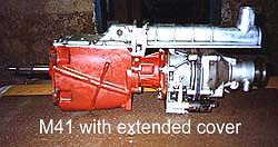 There are two basic schemes: the "short" cover (as found in the Amazon, for instance), which uses a very long, angled shift lever directly mounted into the top of the cover itself, and the "extended" cover (the 1800 type), which mounts a short shift lever well behind the transmission case and couples it via a rod to the same internals. There are several variations of both types of cover depending on year and application, but all will interchange without mechanical difficulty.
 The input shaft slips into the case from the front and is supported by a large ball bearing pressed onto the shaft. It is retained by a bearing cover, which contains the front oil seal, bolted to the case. 4th gear is part of this solid shaft and cannot be removed from it. Whenever the clutch is engaged, the input shaft turns at engine RPM.
 The countershaft is also a solid piece consisting of four gears which correspond to the four forward speeds of the car. It is supported in the bottom of the case by a single spindle (driven clear through the case from front to back) with roller bearings at either end. No matter which gear the driver selects, power is always coupled to the countershaft by the solid 4th gear on the input shaft and the countershaft always drives the remaining forward gears on the mainshaft.
 The mainshaft assembly slips into the case from the rear. The back end is supported by a large ball bearing pressed into a housing which bolts to the case (the M41 housing does nothing but hold the bearing; the M40 housing also contains the speedo drive mechanism and rear oil seal). The front of the mainshaft slips into the rear of the input shaft, where it is supported by roller bearings. The 3rd, 2nd and 1st gears (front to back) are part of the mainshaft assembly, but are separate pieces which spin independently of the shaft itself. As these are always driven by the countershaft, forward gear selection is accomplished by locking only one at a time to the mainshaft itself.