
|
Archive Index | Current Issue | |
|
|
||
Cameron Lovre volvorelix@yahoo.com
Here at VClassics, we get a fair amount of e-mail asking about breakerless ignition systems. Seems that lots of people who drive old Volvos would like to do away with the old-school points and condensor systems that Volvo used up until 1974. There are two common aftermarket systems that accomplish this, the Perlux/Pertronix and the Crane/Allison, each with its own merits as well as its own drawbacks.
This isn't about either of those.
In 1975, Volvo introduced to the U.S. market a new model: the now legendary 240. The first year 240 still used a pushrod B20 engine; but more interesting than that, it came with a breakerless ignition system made by Bosch. We'd heard of people retrofitting this system into the earlier models and decided to try this ourselves.
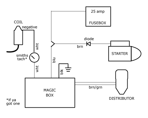
It should be noted that these details are specific to those Volvos that use the infamous "armored cable" connection from the ignition switch to the + terminal on the coil.
We needed a test mule. A car that would be okay if it broke down by the side of the road in the dark while it was raining. Shayne volunteered his wife Sarah's car.
If you are using the original coil (or similar, like a Bosch "blue" coil), you don't need the ballast -- it's already built into the coil. If you plan to use the 1975 coil, you'll want to use the ballast resistor with it.
Next, you'll need a wire with an inline diode that will allow electricity to flow only in one direction. You can get these at Radio Shack if you like, but we bought ours from IPD (already soldered and shrink wrapped!); part number E106, $10.
In the interest of keeping this short, we won't bore you with how many different websites, wiring diagrams or parts cars we studied while we tried to figure out which wires went where. Shayne is smarter with wires than I, so he did the thinking part while I stood around and crimped wires on terminals.
There's a brown and a green wire trapped together in their own loom -- this one's pretty obvious. If you pulled the kit off a car yourself, you'll remember that they connect to the distributor and with that junction block on the end, that's the only place they can go.
Now's a good time to install the distributor. Once that's done, we can turn our attention to the wires that come out of the "black box:"
If your Volvo has a factory-style tach, it will have a white wire that connects to the distributor and another that connects to the coil. The tach circuit goes in series, so that the tach itself is between the black box and the negative terminal. To clarify: the white wire from the box that would normally connect to the negative terminal on the coil should instead connect to the (condensor end) of the white wire that's on the tach, and the coil end of the tach wire remains on the coil's negative terminal.
We've been told (but cannot confirm) that the length of the white wire connected to the tach is important. The story is that changing the length can affect the signal to the tach and cause it to become (more) inaccurate.
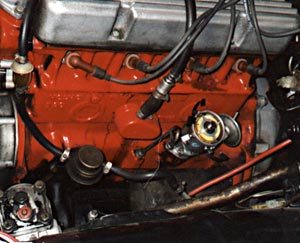
 You're done. Connect the battery and see if anything starts smoking. If not, turn the key to the "on" position and check again. Still no smoke? Start it up and set the timing, and take a test drive. For testing and evaluation, we converted three cars to this Bosch system. On two of the cars, we found that the distributor drive gear had to be turned and reinstalled to allow us to set the timing -- the vacuum retard unit was pressed against the block, preventing adjustment.
|
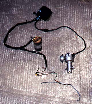 First: get a Bosch system from a parts car. The only candidate parts car is a 1975 240 series. Take the coil (you don't need it, but it's part of the system and handy to have around), the "black box," the distributor, the junction block thingie, the ballast resistor and all the wires that connect 'em up. If you're removing this system from a donor car, collect as much of the attached wiring as you can; this will decrease splicing later.
 About tachometers: Sarah's car has an aftermarket (Bonneville brand -- circa 1960s) tach and nothing about its connections were changed (hot, ground, and negative side of the coil). Many aftermarket tachs work like this and if you have one, you shouldn't have to give it any attention.